For the semi-open impeller basic stage, due to the gap leakage between the impeller cover disc and the stator, the leakage has an important negative impact on efficiency. In this design, the efficiency of the original basic level is not improved. Impeller strength Due to the large single-stage pressure ratio of the compressor, the peripheral speed of the impeller outlet is high, and the impeller strength has been greatly tested. Therefore, the impeller material was selected from high-strength alloy structural steel materials, and re-consideration was made in the structure of the impeller shaft.
The impeller stress calculation uses the stress analysis software cooperating with Xi'an Jiaotong University, which fully complies with the calculation of the axial force of the gear. The series formula has taken into account the combination of static pressure and aerodynamic axial thrust. The end result is axial thrust. This is the rotor with the largest single-stage axial thrust in this model. The compressor still uses the thrust plate on the pinion shaft to transmit the axial thrust generated by the rotor to the large gear shaft, and finally bears the thrust bearing of the large gear shaft. After the balance of the axial force of the gear, the axial force remains first. The strength of the thrust disk must be sufficient, and at the same time, the linear speed difference between the thrust disk on the pinion and the thrust surface of the large gear should be ensured. The thrust bearing adopts the Mitchell type according to the characteristics of large axial force, which improves the bearing capacity of the thrust bearing.
Due to structural constraints, the Mitchell bearing does not use the original Mitchell bearing and thrust bearing structure of our factory, but the support part is in the middle and the thrust pad is on the two sides, making the whole thrust bearing compact. The adjustment method adopts the method of importing the regulating blade to adjust the performance of the compressor, so as to meet the user's use requirements within a certain range. The electric actuator is used to drive the inlet adjustment vanes, and the adjustment vanes are manufactured by precision casting. When the product was tested at the manufacturing plant, the Shenyang area was in winter, comparing the design value with the experimental value performance curve. Through the comparison of the data and the graph, the measured performance curve is in agreement with the expected curve in the flow range, and the efficiency is basically in accordance with the design value, but the measured curve is steep.
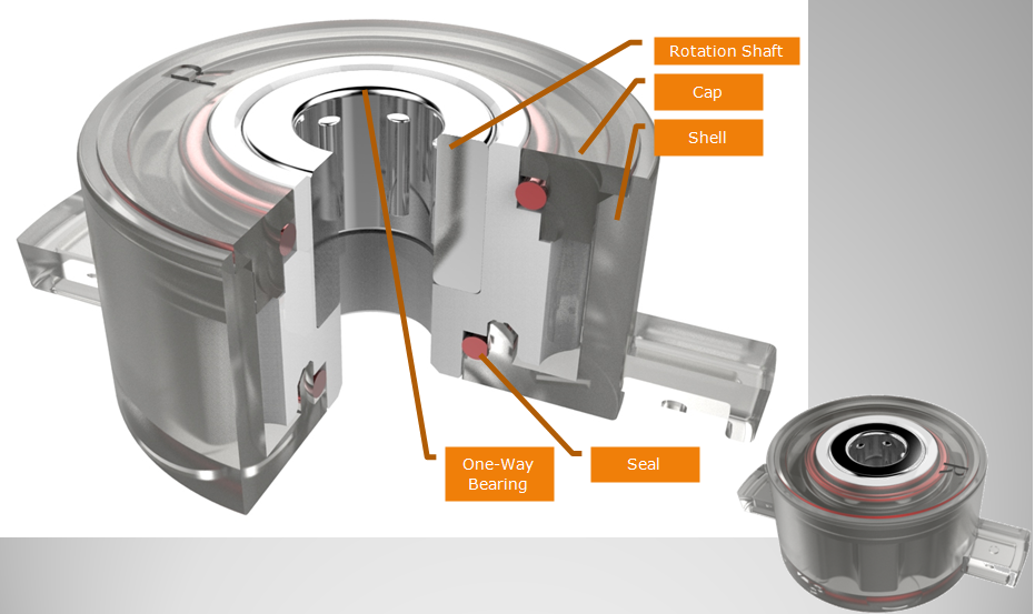
The design of middle through hole is easy to install, Barrel Damper is usually used in small spaces. ABD barrel dampers are the perfect solution for a wide range of applications. Barrel dampers are widely used in automobile interior decoration, household electric appliances, furniture, hidden socket, etc. Our dampers can make the movement of structures soft, quiet and safe to mitigate the impact, avoid the damage, increase the mechanical life, reduce noise, and improve product quality.

NOTE:
1. Please contact the corresponding product engineer for specific torque products.
2. Max. rotation speed: 50r/min
3. Max. circle rate: Clockwise180 °, 180 ° anti-clockwise for 1 cycle
4. Operating temperature: -10~50℃
5. Storage temperature:-30~60℃

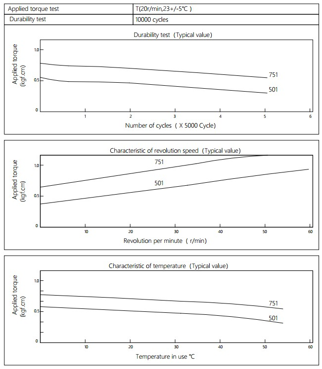
Applied torque:(T)
Test Temperature:23+/-5℃
Rotating speed:20r/min
Durability test Method:Clockwise 180 °, 180 ° anti-clockwise
Rotating speed:20r/min
Test Frequency:1cycle/min
Test Temperature:23±5℃
Durability test cycle:10000 cycle
Test result criteria: Store in the room temperature for 24 hours or more after the test, recording to the torque T=T±30%T.
Barrel Damper
Barrel Damper,Plastic Dampers,Manual Barrel Damper,Toilet Seat Damper,Plastic Barrel Rotary Damper
Shenzhen ABD Equipment Co., Ltd. , http://www.abddamper.com