Hall effect is a kind of magnetoelectric effect. This phenomenon was discovered by Hall (AH Hall, 1855-1938) in 1879 when he studied the conductive mechanism of metal. Later, it was found that semiconductors, conductive fluids, etc. also have this effect, and the Hall effect of semiconductors is much stronger than metals. Hall elements made using this phenomenon are widely used in industrial automation technology, detection technology, and information processing. aspect. Hall effect is the basic method for studying the properties of semiconductor materials. The Hall coefficient measured by the Hall effect experiment can determine important parameters such as conductivity type, carrier concentration, and carrier mobility of the semiconductor material. The Hall effect in the fluid is the theoretical basis for the study of "magneto fluid power generation." According to the principle of Hall effect, the magnitude of the Hall potential depends on: Rh is a Hall constant, which is related to the semiconductor material; IC is the bias current of the Hall element; B is the strength of the magnetic field; d is the thickness of the semiconductor material. For a given Hall device, Vh will completely depend on the measured magnetic field strength B.
A Hall element generally has four lead-out terminals, two of which are the input terminals of the bias current IC of the Hall element, and the other two are the output terminals of the Hall voltage. If the two output terminals form an outer loop, Hall current will be generated. Generally, the setting of the bias current is usually given by an external reference voltage source; if the accuracy requirements are high, the reference voltage source is replaced by a constant current source. In order to achieve high sensitivity, Hall sensors are equipped with high-permeability permalloy on the sensor surface; this type of sensor has a large Hall potential, but it saturates around 0.05T and is only suitable for low-level applications. For use on a small scale. In recent years, due to the rapid development of semiconductor technology, various types of new integrated Hall elements have emerged. Such components can be divided into two major categories. One is a linear component and the other is a switching component.
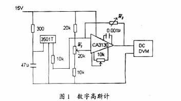
The principle of the linear Hall element UGN350lT is a more commonly used three-terminal linear Hall element. It consists of a voltage regulator, a Hall generator, and an amplifier. With UGN350lT can be easily composed of a gaussmeter. Its use is very simple, first make B = 0, write down the indication value VOH of the table, and then stick the end of the probe on the measured object and record the new indication VOH1. ΔVOH=VOH1-VOH, if ΔVOH>0, it indicates that the end face of the probe is measured as the N pole; otherwise it is the S pole. The sensitivity of the UGN3501T is 7V/T, from which the measured magnetic induction B can be measured. If a digital voltmeter (DVM) is used, the linear gauss meter shown in Fig. 1 can be obtained. The op amp uses a high precision op amp CA3130. The specific zeroing method of this circuit is: After turning on the power, let B=0, adjust W1 to make the indication of DVM zero, and then use a standard yttrium-aluminum-boron magnetic steel (B=0.1T) to stick on the end face of the probe. Adjust W2 so that the indication of DVM is 1V. When the gauss meter shows a value of -200mV, the end of the probe detects the S pole, and the magnetic field strength is 0.02T. The gaussmeter can also be used to measure alternating magnetic fields, but the DVM should be changed to an AC voltmeter. It is clear that the circuit of Figure 1 can be used to easily extend the functionality of a normal digital multimeter.
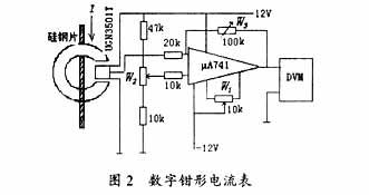
With the UGN3501T can also be easily formed as shown in Figure 2 clamp current meter. The Hall element is placed in the gap of the clamp cold rolled silicon steel sheet. When a current flows through the wire, a magnetic field is generated in the clamp ring, which is proportional to the number of ampere turns passing through the wire current; this magnetic field Acting on the Hall element, the corresponding Hall potential is induced. The sensitivity is 7V/T. After the amplifier is μA741, it is zeroed. After linear amplification, it is sent to the DVM to form a digital clamp ammeter. The debug of this table is very simple too: When the electric current in the wire is zero, adjust W1, W2 to make the indication of DVM be zero. Then input the current of 50A, adjust W3 to make DVM read 5V; Reverse input -50A, the digital value is -5V. Repeated adjustment of W1, W2, W3, readings can meet the requirements. The clamp ammeter after the experiment, the sensitivity is not less than 0.1V/A, the same, this ammeter can also be used for the measurement of alternating current, the DVM can be replaced by an alternating voltage meter can be very convenient.
Honeywell Sensor Applications and Applications in the Electric Bicycle Industry Hall sensors are very widely used and have made significant contributions in aerospace technology, medical technology, transportation, industry, and measurement and testing. The current application area is more active in the field of electric bicycles. This is all due to Honeywell's high-quality four-Hole element. Other high-sensitivity Hall-effect latches use dual Hall or single Hall elements, which makes it very sensitive to package stress, and four Hall elements make these sensors more stable and excellent. These new high-sensitivity latches are specifically designed for brushless DC motors. Its features include: wide temperature range, high sensitivity, compact design (SOT-23 and TO-92 packages available for customers' choice), bipolar latching magnetics, which maintains performance over the entire operating temperature range Stable), wide voltage range, built-in reverse voltage function, ROHS-compliant materials, all of these excellent characteristics are important for brushless current motors in a variety of industrial applications. Honeywell sensors are equipped with reliable high magnetic sensitivity switching points, and no chopper stabilization technology is used on their Hall elements. These features that Horny possesses allow the sensor to output a complete signal, shortening the latch response time to 20 microseconds.
There are three lead wires for the electric vehicle: the power supply (thin red +5V), the ground wire (thin black), and the speed-adjusting signal line (linearly continuously changing the signal in small green). There are two kinds of photoelectric switches and Hall turn handles used in electric vehicles, and the majority of electric vehicles currently adopting Halle's turns are used. Common linear Hall element models are: AH3503AH49EA3515A3518SS495 Such as: AH3503 linear Hall circuit consists of voltage regulator, Hall voltage generator, linear amplifier and emitter follower, its input is the magnetic induction intensity, the output is proportional to the input amount Voltage. The static output voltage (B=0GS) is about half of the supply voltage. S poles appear on the hall sensor marking surface and will drive the output above zero level; N poles will drive the output below zero level; instantaneous and proportional output voltage levels determine the flux density at the most sensitive surface of the device. Raising the supply voltage increases sensitivity. Product features: small size, high accuracy, high sensitivity, good linearity, good temperature stability, and high reliability. The output voltage of the Hall switch is determined by the strength of the magnetic field around the Hall element. Turning the handle changes the magnetic field around the Hall element, which in turn changes the output voltage of the Hall switch.
There are the following signals from the Hall switch used in electric vehicles:
Turning the output voltage of the type of the switch, it is supplying /5V power, and it supplies 5/5V,
Single Hall turn handles 1.1-4.2 (maximum)/4.2-1.1 (few);
Single Hall turn to 2.6-3.7 (rare)/3.7-2.6;
Single Hall turn to 1-2.5/2.5-1;
Single Hall turn to 2.5-4/4-2.5;
Double Hall turn to 0-5/5-0;
Photoelectric turn 0-5 (few)/5-0.
One of the most commonly used is the following two signal transitions: 1-4.2V (commonly referred to as positive) and 4.2-1V (commonly known as the inverse). Among the two signal transitions, the transitions from 1.0V to 4.2V dominate. There are few other output voltage shifts in the market and it has become a non-standard product in fact. This kind of non-standard transmission is used more often in early electric vehicles. Therefore, most controllers currently on the market are products that recognize 1-4.2V turn signals. When the electric vehicle's handle or controller needs to be replaced, once it encounters a situation in which the turn signal and the controller do not match, this requires a change of the turn handle so that the output signal can match the controller. Turn the output signal to reconstruct: to open the transfer, change the polarity of the magnet inside the switch handle, you can change the potential of the output of the switch. If there are two magnets in the turn, respectively, the two magnets are turned 180 °, and then installed; if there is only one magnet in the turn, take out the magnet, reverse 180 °, install the handle, In this way, the starting position of the working magnetic field of the Hall element in the turning handle is changed, thereby realizing the reconfiguration of the output signal of the turning handle. A mechanical switch button is added to the handle that locks the turn and can be used as a mode change button under the control of the controller for mode conversion of 1:1 power assist, electric, constant speed, and fault self-test.
The Hall sensor responds to the turning signal of the electric vehicle brake lever, which is the driving signal of the rotation of the electric vehicle motor. The braking signal is the braking signal that the motor stops rotating. The electric vehicle standard requires that when the electric vehicle brakes and brakes, the controller should be able to automatically cut off the power supply to the motor. Therefore, the electric brake lever should have a brake lever position sensing element. When the brake lever is pinched, the brake signal is transmitted to the controller. After the controller receives the brake signal, the power supply to the motor is stopped immediately.
The position sensor elements of the electric brake lever include mechanical micro-switches (two kinds of mechanical normally open and mechanical normally closed) and switch-type Hall-effect sensing elements (two types of low brake and high brake). The mechanical switch type has two leads, one connected to the negative pole and the other to the disconnected wire, suitable for a low-level brake controller. For controllers that support high levels of braking, one +12V is connected and the other wire is disconnected. Hall-type three lead wires are: brake wire (fine blue +5V), negative electrode (fine black), and the remaining one is broken wire. Common unipolar switch Hall element models are: AH41/AH3144/A3144/A3282.
Normally, the normally open brake signal of the machine is always high. When the brake is applied, the microswitch inside the brake is closed and its signal becomes low. Normally, the normally closed brake signal of the machine is normally low. When the brake is applied, the microswitch inside the brake switch is turned on, and the signal becomes high. The brake signal of the general electronic low-potential brake is a constant high potential. When the brake is applied, the signal of the Hall element within the brake turns over and the signal becomes low. The brake signal of the general electronic high-potential brake is normally low. When the brake is applied, the signal of the Hall element within the brake turns over and the signal becomes high. The change in the level of the brake signal is the controller's identification of whether the electric vehicle is in a braking state, thereby determining whether the controller powers the motor. When the brake knob or controller of an electric vehicle needs maintenance or replacement, it will encounter a situation that the brake signal does not match the controller. This requires the brake handle to be modified so that the output signal can match the controller. Therefore, in the maintenance practice, regardless of the form of the brake lever, and regardless of what kind of brake signal the controller recognizes, it should be able to properly improve the various forms of brake signals to match the signals that the controller can recognize.
A Hall element generally has four lead-out terminals, two of which are the input terminals of the bias current IC of the Hall element, and the other two are the output terminals of the Hall voltage. If the two output terminals form an outer loop, Hall current will be generated. Generally, the setting of the bias current is usually given by an external reference voltage source; if the accuracy requirements are high, the reference voltage source is replaced by a constant current source. In order to achieve high sensitivity, Hall sensors are equipped with high-permeability permalloy on the sensor surface; this type of sensor has a large Hall potential, but it saturates around 0.05T and is only suitable for low-level applications. For use on a small scale. In recent years, due to the rapid development of semiconductor technology, various types of new integrated Hall elements have emerged. Such components can be divided into two major categories. One is a linear component and the other is a switching component.
The principle of the linear Hall element UGN350lT is a more commonly used three-terminal linear Hall element. It consists of a voltage regulator, a Hall generator, and an amplifier. With UGN350lT can be easily composed of a gaussmeter. Its use is very simple, first make B = 0, write down the indication value VOH of the table, and then stick the end of the probe on the measured object and record the new indication VOH1. ΔVOH=VOH1-VOH, if ΔVOH>0, it indicates that the end face of the probe is measured as the N pole; otherwise it is the S pole. The sensitivity of the UGN3501T is 7V/T, from which the measured magnetic induction B can be measured. If a digital voltmeter (DVM) is used, the linear gauss meter shown in Fig. 1 can be obtained. The op amp uses a high precision op amp CA3130. The specific zeroing method of this circuit is: After turning on the power, let B=0, adjust W1 to make the indication of DVM zero, and then use a standard yttrium-aluminum-boron magnetic steel (B=0.1T) to stick on the end face of the probe. Adjust W2 so that the indication of DVM is 1V. When the gauss meter shows a value of -200mV, the end of the probe detects the S pole, and the magnetic field strength is 0.02T. The gaussmeter can also be used to measure alternating magnetic fields, but the DVM should be changed to an AC voltmeter. It is clear that the circuit of Figure 1 can be used to easily extend the functionality of a normal digital multimeter.
With the UGN3501T can also be easily formed as shown in Figure 2 clamp current meter. The Hall element is placed in the gap of the clamp cold rolled silicon steel sheet. When a current flows through the wire, a magnetic field is generated in the clamp ring, which is proportional to the number of ampere turns passing through the wire current; this magnetic field Acting on the Hall element, the corresponding Hall potential is induced. The sensitivity is 7V/T. After the amplifier is μA741, it is zeroed. After linear amplification, it is sent to the DVM to form a digital clamp ammeter. The debug of this table is very simple too: When the electric current in the wire is zero, adjust W1, W2 to make the indication of DVM be zero. Then input the current of 50A, adjust W3 to make DVM read 5V; Reverse input -50A, the digital value is -5V. Repeated adjustment of W1, W2, W3, readings can meet the requirements. The clamp ammeter after the experiment, the sensitivity is not less than 0.1V/A, the same, this ammeter can also be used for the measurement of alternating current, the DVM can be replaced by an alternating voltage meter can be very convenient.
Honeywell Sensor Applications and Applications in the Electric Bicycle Industry Hall sensors are very widely used and have made significant contributions in aerospace technology, medical technology, transportation, industry, and measurement and testing. The current application area is more active in the field of electric bicycles. This is all due to Honeywell's high-quality four-Hole element. Other high-sensitivity Hall-effect latches use dual Hall or single Hall elements, which makes it very sensitive to package stress, and four Hall elements make these sensors more stable and excellent. These new high-sensitivity latches are specifically designed for brushless DC motors. Its features include: wide temperature range, high sensitivity, compact design (SOT-23 and TO-92 packages available for customers' choice), bipolar latching magnetics, which maintains performance over the entire operating temperature range Stable), wide voltage range, built-in reverse voltage function, ROHS-compliant materials, all of these excellent characteristics are important for brushless current motors in a variety of industrial applications. Honeywell sensors are equipped with reliable high magnetic sensitivity switching points, and no chopper stabilization technology is used on their Hall elements. These features that Horny possesses allow the sensor to output a complete signal, shortening the latch response time to 20 microseconds.
Electric vehicle control experiment diagram
Hall sensor on the electric vehicle speed control switch to the name as the name suggests is the electric vehicle speed control components, which is a linear speed control components, many styles but the working principle is the same. It is generally located on the right side of the electric vehicle, which is the direction of the right hand while riding, and the degree of rotation of the electric vehicle turning handle is between 0-30 degrees. Signal characteristics of turn handle and brake handle: The form, signal characteristics, and signal of the turn handle. There are three lead wires for the electric vehicle: the power supply (thin red +5V), the ground wire (thin black), and the speed-adjusting signal line (linearly continuously changing the signal in small green). There are two kinds of photoelectric switches and Hall turn handles used in electric vehicles, and the majority of electric vehicles currently adopting Halle's turns are used. Common linear Hall element models are: AH3503AH49EA3515A3518SS495 Such as: AH3503 linear Hall circuit consists of voltage regulator, Hall voltage generator, linear amplifier and emitter follower, its input is the magnetic induction intensity, the output is proportional to the input amount Voltage. The static output voltage (B=0GS) is about half of the supply voltage. S poles appear on the hall sensor marking surface and will drive the output above zero level; N poles will drive the output below zero level; instantaneous and proportional output voltage levels determine the flux density at the most sensitive surface of the device. Raising the supply voltage increases sensitivity. Product features: small size, high accuracy, high sensitivity, good linearity, good temperature stability, and high reliability. The output voltage of the Hall switch is determined by the strength of the magnetic field around the Hall element. Turning the handle changes the magnetic field around the Hall element, which in turn changes the output voltage of the Hall switch.
There are the following signals from the Hall switch used in electric vehicles:
Turning the output voltage of the type of the switch, it is supplying /5V power, and it supplies 5/5V,
Single Hall turn handles 1.1-4.2 (maximum)/4.2-1.1 (few);
Single Hall turn to 2.6-3.7 (rare)/3.7-2.6;
Single Hall turn to 1-2.5/2.5-1;
Single Hall turn to 2.5-4/4-2.5;
Double Hall turn to 0-5/5-0;
Photoelectric turn 0-5 (few)/5-0.
One of the most commonly used is the following two signal transitions: 1-4.2V (commonly referred to as positive) and 4.2-1V (commonly known as the inverse). Among the two signal transitions, the transitions from 1.0V to 4.2V dominate. There are few other output voltage shifts in the market and it has become a non-standard product in fact. This kind of non-standard transmission is used more often in early electric vehicles. Therefore, most controllers currently on the market are products that recognize 1-4.2V turn signals. When the electric vehicle's handle or controller needs to be replaced, once it encounters a situation in which the turn signal and the controller do not match, this requires a change of the turn handle so that the output signal can match the controller. Turn the output signal to reconstruct: to open the transfer, change the polarity of the magnet inside the switch handle, you can change the potential of the output of the switch. If there are two magnets in the turn, respectively, the two magnets are turned 180 °, and then installed; if there is only one magnet in the turn, take out the magnet, reverse 180 °, install the handle, In this way, the starting position of the working magnetic field of the Hall element in the turning handle is changed, thereby realizing the reconfiguration of the output signal of the turning handle. A mechanical switch button is added to the handle that locks the turn and can be used as a mode change button under the control of the controller for mode conversion of 1:1 power assist, electric, constant speed, and fault self-test.
The Hall sensor responds to the turning signal of the electric vehicle brake lever, which is the driving signal of the rotation of the electric vehicle motor. The braking signal is the braking signal that the motor stops rotating. The electric vehicle standard requires that when the electric vehicle brakes and brakes, the controller should be able to automatically cut off the power supply to the motor. Therefore, the electric brake lever should have a brake lever position sensing element. When the brake lever is pinched, the brake signal is transmitted to the controller. After the controller receives the brake signal, the power supply to the motor is stopped immediately.
The position sensor elements of the electric brake lever include mechanical micro-switches (two kinds of mechanical normally open and mechanical normally closed) and switch-type Hall-effect sensing elements (two types of low brake and high brake). The mechanical switch type has two leads, one connected to the negative pole and the other to the disconnected wire, suitable for a low-level brake controller. For controllers that support high levels of braking, one +12V is connected and the other wire is disconnected. Hall-type three lead wires are: brake wire (fine blue +5V), negative electrode (fine black), and the remaining one is broken wire. Common unipolar switch Hall element models are: AH41/AH3144/A3144/A3282.
Normally, the normally open brake signal of the machine is always high. When the brake is applied, the microswitch inside the brake is closed and its signal becomes low. Normally, the normally closed brake signal of the machine is normally low. When the brake is applied, the microswitch inside the brake switch is turned on, and the signal becomes high. The brake signal of the general electronic low-potential brake is a constant high potential. When the brake is applied, the signal of the Hall element within the brake turns over and the signal becomes low. The brake signal of the general electronic high-potential brake is normally low. When the brake is applied, the signal of the Hall element within the brake turns over and the signal becomes high. The change in the level of the brake signal is the controller's identification of whether the electric vehicle is in a braking state, thereby determining whether the controller powers the motor. When the brake knob or controller of an electric vehicle needs maintenance or replacement, it will encounter a situation that the brake signal does not match the controller. This requires the brake handle to be modified so that the output signal can match the controller. Therefore, in the maintenance practice, regardless of the form of the brake lever, and regardless of what kind of brake signal the controller recognizes, it should be able to properly improve the various forms of brake signals to match the signals that the controller can recognize.
Various products of Two-For-One Twister Machine, providing product images and basic parameters with each Twister Machine and Two-For-One Twister; We are a professional Chinese manufacturer of Two-For-One Twister Machine, and look forward to your cooperation! Our Two-for-one twister machine achieves one turning two twisting. Its efficeincy is higher than traditional machine in times. Take-up volume increasing, no piecing in ten kilometers, twisting quality highly improved.
Two-For-One Twister Machine
Two-For-One Twister Machine,Pp Yarn Two-For-One Twister Machine,Two-For-One Twister Tfo Twisting Machine,Two-For-One Twister Machine For Short Fiber
Xinchang Jinxing Machinery , http://www.xcjinxing.com