When the DC system is subject to some interference, such as the occurrence of DC grounding or the AC power supply stringing into the DC loop, the presence of a long cable-to-ground distributed capacitance effect may often result in the malfunction of some sensitive protection relays. This is fully illustrated by the accidental tripping of a high-voltage shunt reactor in a 500kV substation.
I. Accident Situation Introduction In this 500kV substation, a 500kV line switch equipped with a high-voltage shunt reactor tripped. When the on-duty personnel inspected the relay protection signal, they discovered that the trip unit of the body protection in the high-voltage shunt reactor protection had an exit drop signal. In addition, no other protection action signals were found. The operating personnel checked the high-voltage shunt reactor body and found no abnormalities. The fault current or fault voltage waveform was not seen on the wave chart, indicating that there was no accident at that time, and no one was on the line before the trip. Line protection and high voltage shunt reactor protection circuit work.
2. Analysis of the cause of the accident After the accident, the protection professional quickly organized an inspection of the high-voltage shunt reactor protection. The focus of the inspection is on the body protection part of its protection. The body protection circuit is shown in Figure 1.
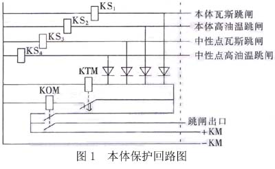
KS1, KS2, KS3, and KS4 are drop relays and indicate the body protection action signal. When the relay trips, the four relays do not drop the card. KOM is the body protection relay intermediate relay, and the contact initiates the body trip unit. KTM is the time relay. Its function is to make the KOM keep a fixed action time regardless of the closing time of the body trip signal after receiving the body trip signal, so as to ensure reliable switch tripping.
The inspection and test of the high-voltage shunt reactor body protection has not been found to have enough defects in the relay protection and secondary circuit to cause protection against malfunction. However, due to the fact that the trip unit protected by the body does have an exit drop signal, the possibility of false exit from the body protection is very high. Since the trip exit relay and the drop relay of the trip unit 3 can be started at the same time, there is only one pair of contacts of the KOM relay shown in FIG. 1; it is basically possible to recognize that the contact of the KOM relay is closed due to the loop. Big.
Protection professionals found three conditions during the inspection.
a. KOM operation voltage is too low, the action value is DC28V, and its operating time is 3ms under rated voltage.
b. The input loop of the body protection relay is activated by a long cable leading from an open air contact. The cable length is approximately 500m and is the longest secondary control cable in the substation. The cable is a shielded cable. Both ends of the shield are grounded in the switchyard and control room.
c. At the same time as the accident trips, the DC system of the substation fluctuates. This signal from the DC insulation monitoring device can be confirmed.
Therefore, after repeated scrutiny, only the assumption is made that the control cable for introducing the body signal is very long, and the core wire of the cable has a large distributed capacitance to the shielding layer (grounded on both sides of the shielding layer). When the DC positive power supply is grounded or the AC power supply is connected in series to the DC loop, the relay will be activated due to the effect of the long cable-to-ground distributed capacitance. After the specific analysis, it is considered that there are 3 kinds of situations, each of which may cause the KOM's action to exit.
a. Substation DC power (battery) positive bus ground. After grounding occurs, the DC power supply of the substation charges the distributed capacitance between the cable core and the shielding layer through the coil of the KOM, and a capacitor charging current flows in the coil thereof. If the charging current is large enough and the charging time is long enough, it may make the contact of the more sensitive KOM momentarily close. Once the contact is closed, the coil will pass through its own pair of contacts and a pair of KTM contacts. The self-holding circuit is constructed to hold the operation for a period of time (holding time is the setting time of KTM), thereby starting the tripping outlet circuit and causing the circuit breaker to trip.
b. The AC power to the ground is connected in series to the positive bus of the DC power system. If there is an AC power supply connected in series to the positive power supply side of the DC power supply system, a loop can be formed by the distributed capacitance between the KOM coil, the battery, and the cable core and the shielding layer, and the KOM coil has a capacitor current flowing therethrough. If the capacitor current is large enough, it is possible to start the KOM and cause its contacts to dither. As long as the KOM contact is once closed, it will form a self-holding circuit for a certain period of time (kT setting time) by using its own pair of contacts and a pair of KTM contacts to start the tripping outlet circuit, causing a secondary circuit. Trip. Different from the previous case, as long as the AC power does not disappear, after the KOM and the KTM both return, the above operation process will be repeated again until the AC power disappears.
c. Connect the AC power supply to the negative bus of the DC power system. If there is an AC power supply connected in series to the negative power supply side of the DC power supply system, a loop can be formed by the distributed capacitance between the coil and the cable core and the shielding layer of the KOM, and the coil has a capacitive current flowing therethrough. The same situation as b occurs.
The above three kinds of situations are in the end, whether they are possible, and need to be verified through trials.
Third, the test 3.1 analog DC positive power + KM grounding test Figure 2 shows the simulation of DC positive power + KM grounding test, R1, R2 in the figure for the DC system to ground insulation resistance.
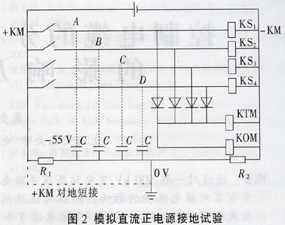
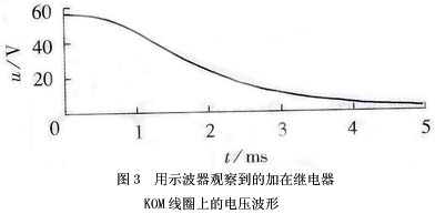
The substation DC voltage is 110V, +KM is +55V to ground, and -KM is -55V to ground. Under normal conditions, points A, B, C, and D are -55V to ground potential. If +KM is shorted to ground, +KM will become 0V to ground, -KM will change to -110V, and points A, B, C, and D will not mutate due to the effect of capacitance. The short circuit is still -55V. In this way, at the beginning of the short circuit, a voltage of 55V is generated at both ends of the relay coil, and then the capacitor is charged through the relay coil, that is, the point A, B, C, and D gradually change from -55V to -110V. The voltage across the relay coil also gradually changes from -55V to 0V. Observe the voltage across the KOM with an oscilloscope. The waveform is shown in Figure 3.
If the DC test power supply is increased to 220V, the KOM is activated and the drop-out relay has a high operating value, so it does not act. This is the same situation as in the case of a fault. However, because the substation direct current is 110V, the required DC system voltage 220V cannot be achieved during operation. Therefore, it can be determined that the fault is not caused by the grounding of the DC positive power supply due to insufficient grounding of the DC positive power supply to cause protection misoperation.
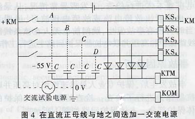
3.2 Superimposed AC voltage between analog DC positive bus and ground. Figure 4 shows an overlay of AC power supply test between analog DC bus and ground. An AC voltage is superposed between the DC positive bus and the ground, and the AC voltage gradually increases from small to large. When the AC voltage reaches 100V, the KOM operates and the body protection action is exactly the same as the trip condition at the time, ie, only the outlet relay operates, and the body swapping card does not move. When the AC voltage is increased to 220V, the operation is still the same. This indicates that tripping accidents may occur if the used AC power accidentally hits the DC positive bus side.
3.3 Analog DC superimposed alternating voltage between negative busbars and ground. Figure 5 shows an example of a superimposed AC power supply test between negative DC analog rails and ground.
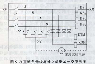
An AC voltage is superposed between the negative DC bus and the ground, and the voltage gradually increases from small to large. When the AC voltage is also reaching 100V, the KOM moves, and the action of the body protection is exactly the same as that at the time of the trip. That is, only the outlet relay operates, and the body swapping card does not move. When the AC voltage is increased to 220V, the operation is still the same. This shows that accidental tripping may occur if the used AC power accidentally hits the DC negative bus side.
The above test results show that in this fault, the charging current of the cable-to-ground distributed capacitance due to the DC positive busbar grounding is insufficient to enable the relay to operate. When the AC power supply is added to the DC system, it is added to the DC positive power supply side or negative. On the power supply side, as long as the AC voltage exceeds 100V, it may cause the relay outlet to move, causing the circuit breaker to trip.
Afterwards, it was ascertained that other workers had indeed mistakenly contacted the AC power with the DC negative power supply, causing the tripping of the 500 kV line switch of the high-voltage shunt reactor. The measured value of the distributed capacitance of this long cable was measured during the test. The measured result is that each core-to-ground capacitance is approximately 0.115 μF, and the total core-to-ground distributed capacitance of the four cores is 0.46 μF.
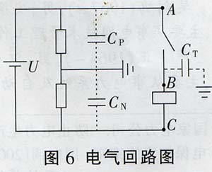
IV. Loop Analysis of Controlled Cable Distribution Capacities Caused by Relay Misoperation The above tests have shown that the long cable leading to the switching location does have a large distributed capacitance between the shields of the core pair, and when the shields at both ends of the cable After grounding, the distributed capacitance of this core to the shield is the distributed capacitance of the cable core to ground. When a DC system is grounded or an AC series is accidentally connected to a DC system, a loop is formed by this distributed capacitance to generate a capacitive current, which causes some sensitive relays with lower operating values ​​to malfunction. There are five scenarios for further analysis.
4.1 Positive power supply of the DC system When the DC positive power supply (point A in Figure 6) is suddenly shorted to ground, the battery charges its distributed capacitance through the relay coil with its 1/2 VDC voltage. This is actually a simple zero-state response under DC excitation.
From the instant when the positive DC power supply is grounded, the voltage UR on the relay coil changes with time t.
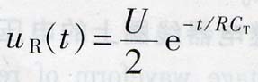
Where R is the resistance of the coil of the relay; CT is the value of the cable distributed capacitance.
At t=0, the voltage UR applied to the relay coil is the maximum, which is U/2, and then gradually decays with time t. It can be seen from the equation that if the relay's operating voltage is higher than half of the DC voltage of the substation (that is, higher than U/2), the relay will not malfunction; if the relay's operating voltage is lower than half of the DC voltage of the substation ( If less than U/2), malfunction may occur.
4.2 Grounding of the Relay Coil Side When the side of the relay coil (point B in Figure 6) is suddenly grounded, the battery charges the distributed capacitance CP and CN of the DC system through the relay coil with a U/2 DC voltage. The voltage UR applied to the relay coil changes with time t as
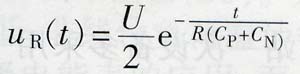
In the formulae, CP and CN are the DC positive and negative bus-to-ground distribution capacitors in the substation.
At t=0, the voltage uR applied to the relay coil is the maximum, which is U/2, and then gradually decays with time t. From the formula can also be seen: if the relay's operating voltage is higher than half of the substation DC voltage (ie, higher than U/2), the relay will not malfunction; at the relay's operating voltage is less than half of the substation DC voltage ( If less than U/2), malfunction may occur.
The larger the CP and CN, the slower the voltage decay. As long as the voltage applied to the relay coil is longer than the relay's operating value during the decay process and exceeds the relay's operating time, the relay will malfunction. The more cable cores leading from the positive and negative power supply sides of the DC system to the switching field, the longer the cable, the larger the distributed capacitances CP and CN.
4.3 When the AC power supply to the ground is connected to the positive and negative DC busbars, when the AC power supply to the ground is connected to the positive DC power supply (point A in Figure 6) or the negative bus (C point in Figure 6), it can pass through the relay coil. , batteries, cables, and distributed capacitors form a loop.
The impedance of the entire loop is Z=R+1/(jωCT)
The voltage applied to the relay coil is uR=us/[1+1/(jωRCT)]
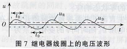
Us is the AC voltage in series, the greater the distributed capacitance CT of the control cable, the greater the effective value of the voltage applied to the relay coil. The voltage waveform on the relay coil is shown in Figure 7.
If the voltage uR applied to the relay coil is higher than the relay operating voltage uD during the change process, the time t0 is long enough for t0 to exceed the relay operating time, and the relay will malfunction.
4.4 Grounding AC power supply in series with the relay coil (on the cable side)
When there is an AC power supply in series with the relay coil (on the cable side, ie, point B in Figure 6), a loop can be formed by the relay coil and the DC negative power supply side-to-side distributed capacitance CN (DC negative power supply side to ground insulation resistance Very large, can be ignored).
The impedance of the entire loop is Z=R+1/(jωCN)
The voltage applied to the relay coil is uR=us/[1+1/(jωRCN)]
The greater the distributed capacitance CN of the control cable, the greater the effective value of the voltage applied to the relay coil.
The voltage waveform applied to the relay coil is also shown in Figure 7. Similarly, if the voltage uR applied to the relay coil is higher than the relay operating voltage uD during the change process, the time t0 is long enough for t0 to exceed the relay operating time, and the relay will malfunction.
V. Precautionary measures 500kV substation primary equipment uses a half-switching connection mode. Due to the large safety distance between 500kV devices and the large number of devices, the main transformer, especially the line-connected high-voltage reactor, is far away from the control room. The length of the secondary control cable is Sometimes as long as 400 ~ 500m, its secondary control cable distribution capacitance effect on the ground is particularly evident. Ignoring the influence of the control cable's distributed capacitance and not taking precautionary measures, it often leads to relay protection misoperation.
It is not difficult to see from the foregoing analysis that the influence of the distributed capacitance of the cable on the ground, resulting in the malfunction of the sensitive relay, depends on three factors:
a. Cable-to-ground distributed capacitance values;
b. The magnitude of the relay action voltage value;
c. External interference factors.
5.1 Decrease the distributed capacitance value of the control cable First, try to control the length of the secondary cable within a certain length. The current design procedure does not specify this and it should not exceed 400m in principle. In the design of substations, multiple substation design methods can be adopted for substations with larger area; if only one protection room is used, the protection room or main control building should be selected as far as possible at the geographical center of the substation. Second, the outdoor high-voltage power distribution device in the substation adopts a GIS power distribution device, which can effectively reduce the substation area and reduce the length of the secondary cable. Third, the separate arrangement of cables for different applications reduces the effect of distributed capacitance. Fourth, the tripping signal is transmitted through the optical fiber tripping channel to eliminate the distributed capacitance effect of the cable.
5.2 Improving the operation value of the DC intermediate relay Once the substation is completed, the position of the primary equipment is fixed. The cable length from the control room to these primary equipments is also determined and basically cannot be changed. Therefore, it is necessary to change the distributed capacitance value of the cable to the ground. Size is very difficult. An effective precaution is to increase the operating value of the relay. In order to pursue sensitivity, it is undesirable to blindly lower the relay's operating value (some protection from foreign imports has this phenomenon). In the accident, the KOM operating voltage is only 28V, which is much lower than half of the DC voltage of the substation. Obviously, it cannot meet the safety requirements in operation. Tests have shown that replacing a relay with a 60V operating voltage will not cause the relay to operate even if the AC voltage in the test is applied to 300V. Therefore, an intermediate relay with a high operating voltage and high operating speed can be selected, which can not only protect the safety but also ensure the sensitivity. In addition, we must pay attention to the selection of DC voltage in the control loop. The 48V DC loop should not be extended to outdoor.
5.3 Avoiding the influence of external interference factors as much as possible When designing and constructing secondary cables, it is necessary to avoid having mixed AC and DC loops on the same secondary cable, and to make distances between strong and weak cables. When designing the terminal block arrangement, a blank terminal should be used for separation between AC and DC circuits.
VI. Conclusion In a relay protection circuit composed of static relays, when a DC system is grounded or an AC series is mistakenly connected to a DC system, the relay coil will form a loop through the distributed capacitance of the cable, generating a capacitive current. Whether the capacitor current can cause the relay to malfunction depends on the distributed capacitance value of the cable to the ground and the operation value of the relay. The precautionary measures are mainly considered from three aspects: reducing the distributed capacitance of the secondary cable, selecting a relay with a higher operating value, and avoiding external factors to interfere with the DC system.
4V series pneumatic valves control airflow by applying electricity to the solenoid. These components are designed to stop, start or change the direction of airflow. Brando offers numerous port and position configurations. Most air control valves are available with AC220V, DC24V, AC110V, AC24V or DC12V solenoid coils. Choose from the 5/2 way, or the 5/3 way.
Brando Supply: 4V110-06, 4V120-06, 4V210-06, 4M220-06, 4V210-08, 4V220-08, 4V310-08, 4V320-08, 4V310-10, 4V410-15, 4V420-15, 4V130C-06, 4V130E-06, 4V130P-06, 4V230C-06, 4V230E-06, 4V230P-06, 4V230C-08, 4V230E-08, 4V230P-08, 4V330C-08, 4V330E-08, 4V330P-08, 4V330C-10, 4V330E-10, 4V330P-10, 4V430C-15, 4V430E-15, 4V430P-15.
1. Pilot-oriented mode: optional for internal or external;
2. Structure in sliding column mode: good tightness and sensitive reaction;
3. Three position solenoid valves have three kinds of central function for your choice;
4. Double control solenoid valves have memory function;
5. Internal hole adopts special processing technology which has little attrition friction, low start pressure and long service life;
6. It is available to form integrated valve group with the base to save installation space;
7. Affiliated manual devices are equipped to facilitate installation and debugging;
4V Solenoid Valve, Airtac Solenoid Valve 24VDC, Airtac Pneumatic Solenoid Valve, Airtac 5/2 Way Solenoid Valve
NINGBO BRANDO HARDWARE CO.,LTD , https://www.brandopneumatic.com