Abstract: This paper analyzes the working principle of mass flow, and elaborates the factors affecting the accuracy of the mass flow meter and its correction.
Keywords: mass flow meter, measurement accuracy, factor correction 1 Overview Mass flow meter is a flow measurement instrument with high measurement accuracy and stable and reliable operation. It can directly measure the mass flow of fluid. With the development of socio-economic technology, mass flow meters are increasingly used in field measurement and trade settlement. At present, most of the mass flow meters for trade settlement are products of Emerson. Many people think that mass flow meters measure mass flow, and their measurement accuracy is independent of the temperature and pressure of the measured medium. This view is actually not accurate. Let's make a preliminary discussion below.
The working principle of 2 mass flowmeter When a tube rotates around the origin, let a mass point flow from the origin through the outer end of the tube, that is, the linear velocity of the particle is gradually increased from zero, that is, the particle is energized. The resulting reaction force Fc will slow down the rotation speed of the tube, that is, the tube motion will lag behind. On the contrary, let a mass point flow from the outer end through the tube to the origin, that is, the linear velocity of the particle gradually decreases from large to zero, that is, the energy of the particle is released, and the resulting reaction force Fc will make the tube's The speed of rotation is accelerated, that is, the tube motion advances. This kind of force Fc that causes the speed of the rotating tube to advance or lag is called Coriolis force (see Figure 1).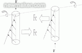
Two identical tubes, which are rotated in the same phase around the same axis, are connected by the same tube to form a U-shaped tube. When there is no particle flow in the pipe, the connecting pipe and the shaft are parallel, and when there is a mass point in the pipe, due to the Coriolis force, the two rotary pipes are out of phase and the connecting pipe is no longer parallel to the shaft (see figure 2). In a word, the phase difference of the pipe depends on the size of the pipe deformation, and the size of the pipe deformation only depends on the size of the fluid flowing through the pipe. This lays a theoretical foundation for the direct measurement of fluid mass flow using Coriolis force.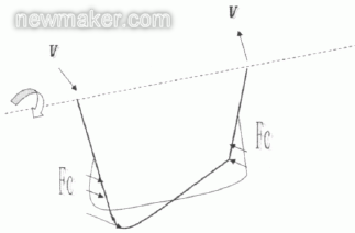
Pipes that are constantly rotating can only be modeled in the laboratory and cannot be used on the actual production site. We cut the circular motion of the tube into a circular arc to make the tube rotate repeatedly within the arc, that is, the one-way rotation motion becomes bidirectional vibration, and when there is flow, it becomes a repeated twist. To achieve tube vibration is very convenient, that is, excitation with excitation current. Electromagnetic induction is used to obtain sine numbers 1 and 2 at both ends of the tube. The magnitude of the phase difference between the two sine numbers directly reflects the mass flow rate (see Figure 3).
The measurement principle can be expressed as a formula:
Fc=2·Δm(ω·υ)
Where Fc - the Coriolis force acting on the measuring tube; Δm - the moving object; ω - the angular velocity; υ - the radial velocity in a rotating or oscillating system.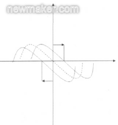
It is easy to see that the magnitude of the Coriolis force depends on the moving object (Δm), its velocity in the system (υ), and thus a function of mass flow.
3 Factors influencing the measurement accuracy of mass flowmeters and corrections There are many factors that affect the measurement accuracy of mass flowmeters, such as the basic error of the instrument, the stability of the zero point, and the repeatability error. These errors can be derived from the design and manufacture of mass flowmeters. Corrected. In addition, mass flowmeters can also cause certain errors during installation and use. For example, if the process temperature is too high, the process pressure is much higher than the test pressure or the surrounding mechanical vibration is strong, the measurement accuracy of the mass flowmeter will be affected.
3.1 Influence and modification of mechanical vibration From the working principle of the mass flow meter, we know that it is a measuring instrument based on the principle of vibration that vibrates at its own frequency. The fluid flowing through the flow tube causes the measurement tube to distort and the degree of distortion is proportional to the mass flow rate. The resonance wave generated by the external mechanical vibration will inevitably interfere with the instrument's own vibration amplitude and frequency, affect the measurement accuracy, and even seriously damage the instrument.
In order to eliminate the impact of mechanical vibration on the accuracy of the instrument, we should pay attention to the installation and use of maintenance.
First of all, the location of the installation should be selected as far as possible in the absence of mechanical vibration, away from the vibration source such as the pump room, the unit and so on. Try to avoid installing two or more sensors on the same pipe, because the vibration of the measuring tube will make each mass flow meter affect each other, causing interference and causing abnormal vibration, which will affect the work of the instrument.
Second, to standardize the instrument installation. Using stress-free installation, the straight pipe shall be directly fixed on the support frame when installing, and the connection part of the flow meter shall be installed, the straight pipe shall be cut according to its proper length, and the flow meter shall be welded without pressure; or the process pipeline shall be The flanges are properly aligned and kept coaxial to reduce stress, and a fixed support frame is provided to prevent the meter from oscillating on longer lines. However, the support frame should be installed on the pipeline outside the flanges of the instrument. Otherwise, if it is directly supported on the instrument itself, it will affect its free oscillation, and the phase difference generated during the oscillation will be deviated, which will affect the measurement results, especially for large-diameter flow. Due to the large amplitude of vibration, the consequences are even more serious.
When it is unavoidable that the sensors are used in series in the same pipeline, the manufacturers should be asked to stagger the resonant frequency values ​​close to the instrument, or to open the sensor installation distance and set up separate support frames.
When a valve or pump is on a process line near a sensor, it needs its own support and cannot be supported by the mounting base of the sensor or the connector of the process.
For shorter or weaker vibrations, corrections can be made by increasing the damping factor. Damping coefficient can be modified by 275 communicator, generally set to 5~30 seconds.
3.2 Effect of process temperature and correction Process temperature changes will cause changes in the volume of the medium, but will not affect the measurement results, because the quality is always conserved regardless of the temperature change. However, changes in temperature can affect the rigidity of the measuring tube and the stability of the zero point, thereby affecting the measurement accuracy of the mass flow meter.
The change of the temperature to the stiffness of the measuring tube is: When the temperature rises, the material of the measuring tube will become soft, otherwise it will become hard, and the distortion produced by the Coriolis force is also affected. However, the flow tube rigidity is reproducible and repairable. RTD temperature sensors are installed in the sensors of general mass flowmeters to perform temperature measurement and temperature compensation. Such as Emerson's mass flowmeter, the measurement tube stiffness with temperature changes can be corrected with the temperature coefficient T.
However, the effect of temperature changes on the stability of the zero point produces an additional error and is non-repetitive. This is due to the imbalance in the material and geometry of the sensor. The sensor's zero instability is due to the maximum deviation that can occur when the media temperature is inconsistent with the zeroing temperature, expressed as the percentage of change in the flow rate of the media when the temperature is changed by 1°C from the zeroing temperature. When there is a big difference between the process temperature and the zero temperature, the error will be more significant. Therefore, in order to reduce the effect of temperature on the stability of the zero point, the instrument can be zeroed at the process temperature.
3.3 Influence of process pressure and modification of process pressure As with temperature changes, the stiffness of the measuring tube changes. As the medium pressure rises, the material of the sensor measuring tube hardens, enhancing (measuring) the stiffening effect of the vibrating tube and the Bourdon effect of the vibrating vibrating tube. The change in pressure causes the sensor's elasticity to deteriorate and the size of the structure to change, thereby affecting the meter's instrument constants. Therefore, the material and geometry of the measuring tube determine the influence of pressure on the sensor. The larger the diameter, the greater the influence.
The effect of pressure on the flowmeter is not only the influence of the fluctuation of the medium pressure on the flowmeter, but also the effect caused by the large deviation of the working pressure and the calibration pressure. At present, the calibration pressure of the flow meter calibration station is generally set at about 0.45 MPa, but the actual working pressure after installation of the mass flow meter is much higher than the calibration pressure. When the working pressure is higher than the calibration pressure, a slight change in the stiffness of the sensor's vibrating tube will cause a negative deviation in the flow rate. Its amplitude has a certain relationship with the thickness and the ratio of the outer diameter of the vibrating tube. The ratio has a high influence and a small ratio, while a low ratio has an effect. Big. The influence of small diameter can be almost ignored, but with the decrease in thickness and diameter ratio of the vibrating tube, the pressure effect still exists.
A meter manufacturer has used experimental methods to test the effect of pressure changes on the measurement accuracy of the meter. The specific method is to use a volumetric tube flow standard device to test a mass flowmeter, install a flowmeter according to the normal verification operating procedures, set a good calibration pressure, adjust the flowmeter zero point, perform the calibration operation, and complete a verification process. ,Reset the calibration pressure and perform the calibration operation again under the new calibration pressure until all the pressure points are tested. Table 1 is the test data of a flow meter under different pressures.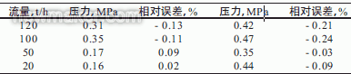
As can be seen from Table 1, the greater the pressure, the greater the relative error. The error is negative, indicating that the flow display value is too small. From the above analysis, it can be seen that the influence of pressure on the mass flow meter measurement is indeed present, so it is necessary to correct it. Instrument manufacturers in the manufacture of mass flow meters, has taken into account the impact of pressure on the measurement accuracy, by increasing the wall thickness of the flow tube to reduce the impact of pressure on the measurement accuracy, but increase the wall thickness will reduce the distortion sensitivity, while the reduction of the distortion sensitivity will reduce Measurement accuracy, so in order to ensure measurement accuracy, the flow tube diameter and wall thickness should be kept at an optimal ratio. Therefore, manufacturers cannot make more technical improvements during manufacturing to eliminate the influence of working pressure on measurement accuracy. To eliminate this effect, it is also necessary to make corrections during use. The simplest method is to agree an average pressure between the supply and demand sides, calculate the compensated flow coefficient, reconfigure in the transmitter, or according to the flow coefficient. The change determines that an average flow meter coefficient directly corrects the results of the flow meter, which can be used when pressure fluctuations are not significant. However, a more scientific and accurate method is to equip the measuring point with a pressure transmitter, and the signal measured by the pressure transmitter is introduced into the mass flow meter transmitter. The mass flow meter performs automatic pressure compensation according to the received signal.
No matter what pressure correction method is used, the transmitter is compensated according to the following formula: K=Kcal·[1-Kp·(Pmeas-Pcal)].
K - flow coefficient after pressure compensation; Kcal - flow coefficient measured off-line before delivery of the flowmeter or before installation; Kp - pressure change compensation coefficient for different types of sensors (see Table 2); Pmeas - Flowmeter Working pressure (gauge pressure), Pa; Pcal - flowmeter offline calibration pressure (gauge pressure), Pa.
In the formula, Kp·(Pmeas-Pcal) obtains the measurement error when the working pressure deviates from the calibration pressure, indicating that the greater the deviation, the greater the error. When the working pressure is relatively stable, a fixed value can be used to correct the measurement error by directly configuring the transmitter. When the working pressure fluctuates greatly, it is recommended to adopt the method of adding a pressure transmitter to measure the pressure online to perform dynamic compensation. .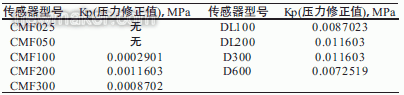
Keywords: mass flow meter, measurement accuracy, factor correction 1 Overview Mass flow meter is a flow measurement instrument with high measurement accuracy and stable and reliable operation. It can directly measure the mass flow of fluid. With the development of socio-economic technology, mass flow meters are increasingly used in field measurement and trade settlement. At present, most of the mass flow meters for trade settlement are products of Emerson. Many people think that mass flow meters measure mass flow, and their measurement accuracy is independent of the temperature and pressure of the measured medium. This view is actually not accurate. Let's make a preliminary discussion below.
The working principle of 2 mass flowmeter When a tube rotates around the origin, let a mass point flow from the origin through the outer end of the tube, that is, the linear velocity of the particle is gradually increased from zero, that is, the particle is energized. The resulting reaction force Fc will slow down the rotation speed of the tube, that is, the tube motion will lag behind. On the contrary, let a mass point flow from the outer end through the tube to the origin, that is, the linear velocity of the particle gradually decreases from large to zero, that is, the energy of the particle is released, and the resulting reaction force Fc will make the tube's The speed of rotation is accelerated, that is, the tube motion advances. This kind of force Fc that causes the speed of the rotating tube to advance or lag is called Coriolis force (see Figure 1).
(Figure 1 Coriolis force diagram of the tube rotation around the origin)
Two identical tubes, which are rotated in the same phase around the same axis, are connected by the same tube to form a U-shaped tube. When there is no particle flow in the pipe, the connecting pipe and the shaft are parallel, and when there is a mass point in the pipe, due to the Coriolis force, the two rotary pipes are out of phase and the connecting pipe is no longer parallel to the shaft (see figure 2). In a word, the phase difference of the pipe depends on the size of the pipe deformation, and the size of the pipe deformation only depends on the size of the fluid flowing through the pipe. This lays a theoretical foundation for the direct measurement of fluid mass flow using Coriolis force.
(Figure 2 Coriolis force diagram of fluid flowing through U-shaped tube)
Pipes that are constantly rotating can only be modeled in the laboratory and cannot be used on the actual production site. We cut the circular motion of the tube into a circular arc to make the tube rotate repeatedly within the arc, that is, the one-way rotation motion becomes bidirectional vibration, and when there is flow, it becomes a repeated twist. To achieve tube vibration is very convenient, that is, excitation with excitation current. Electromagnetic induction is used to obtain sine numbers 1 and 2 at both ends of the tube. The magnitude of the phase difference between the two sine numbers directly reflects the mass flow rate (see Figure 3).
The measurement principle can be expressed as a formula:
Fc=2·Δm(ω·υ)
Where Fc - the Coriolis force acting on the measuring tube; Δm - the moving object; ω - the angular velocity; υ - the radial velocity in a rotating or oscillating system.
(Figure 3 shows the phase difference of vibration)
It is easy to see that the magnitude of the Coriolis force depends on the moving object (Δm), its velocity in the system (υ), and thus a function of mass flow.
3 Factors influencing the measurement accuracy of mass flowmeters and corrections There are many factors that affect the measurement accuracy of mass flowmeters, such as the basic error of the instrument, the stability of the zero point, and the repeatability error. These errors can be derived from the design and manufacture of mass flowmeters. Corrected. In addition, mass flowmeters can also cause certain errors during installation and use. For example, if the process temperature is too high, the process pressure is much higher than the test pressure or the surrounding mechanical vibration is strong, the measurement accuracy of the mass flowmeter will be affected.
3.1 Influence and modification of mechanical vibration From the working principle of the mass flow meter, we know that it is a measuring instrument based on the principle of vibration that vibrates at its own frequency. The fluid flowing through the flow tube causes the measurement tube to distort and the degree of distortion is proportional to the mass flow rate. The resonance wave generated by the external mechanical vibration will inevitably interfere with the instrument's own vibration amplitude and frequency, affect the measurement accuracy, and even seriously damage the instrument.
In order to eliminate the impact of mechanical vibration on the accuracy of the instrument, we should pay attention to the installation and use of maintenance.
First of all, the location of the installation should be selected as far as possible in the absence of mechanical vibration, away from the vibration source such as the pump room, the unit and so on. Try to avoid installing two or more sensors on the same pipe, because the vibration of the measuring tube will make each mass flow meter affect each other, causing interference and causing abnormal vibration, which will affect the work of the instrument.
Second, to standardize the instrument installation. Using stress-free installation, the straight pipe shall be directly fixed on the support frame when installing, and the connection part of the flow meter shall be installed, the straight pipe shall be cut according to its proper length, and the flow meter shall be welded without pressure; or the process pipeline shall be The flanges are properly aligned and kept coaxial to reduce stress, and a fixed support frame is provided to prevent the meter from oscillating on longer lines. However, the support frame should be installed on the pipeline outside the flanges of the instrument. Otherwise, if it is directly supported on the instrument itself, it will affect its free oscillation, and the phase difference generated during the oscillation will be deviated, which will affect the measurement results, especially for large-diameter flow. Due to the large amplitude of vibration, the consequences are even more serious.
When it is unavoidable that the sensors are used in series in the same pipeline, the manufacturers should be asked to stagger the resonant frequency values ​​close to the instrument, or to open the sensor installation distance and set up separate support frames.
When a valve or pump is on a process line near a sensor, it needs its own support and cannot be supported by the mounting base of the sensor or the connector of the process.
For shorter or weaker vibrations, corrections can be made by increasing the damping factor. Damping coefficient can be modified by 275 communicator, generally set to 5~30 seconds.
3.2 Effect of process temperature and correction Process temperature changes will cause changes in the volume of the medium, but will not affect the measurement results, because the quality is always conserved regardless of the temperature change. However, changes in temperature can affect the rigidity of the measuring tube and the stability of the zero point, thereby affecting the measurement accuracy of the mass flow meter.
The change of the temperature to the stiffness of the measuring tube is: When the temperature rises, the material of the measuring tube will become soft, otherwise it will become hard, and the distortion produced by the Coriolis force is also affected. However, the flow tube rigidity is reproducible and repairable. RTD temperature sensors are installed in the sensors of general mass flowmeters to perform temperature measurement and temperature compensation. Such as Emerson's mass flowmeter, the measurement tube stiffness with temperature changes can be corrected with the temperature coefficient T.
However, the effect of temperature changes on the stability of the zero point produces an additional error and is non-repetitive. This is due to the imbalance in the material and geometry of the sensor. The sensor's zero instability is due to the maximum deviation that can occur when the media temperature is inconsistent with the zeroing temperature, expressed as the percentage of change in the flow rate of the media when the temperature is changed by 1°C from the zeroing temperature. When there is a big difference between the process temperature and the zero temperature, the error will be more significant. Therefore, in order to reduce the effect of temperature on the stability of the zero point, the instrument can be zeroed at the process temperature.
3.3 Influence of process pressure and modification of process pressure As with temperature changes, the stiffness of the measuring tube changes. As the medium pressure rises, the material of the sensor measuring tube hardens, enhancing (measuring) the stiffening effect of the vibrating tube and the Bourdon effect of the vibrating vibrating tube. The change in pressure causes the sensor's elasticity to deteriorate and the size of the structure to change, thereby affecting the meter's instrument constants. Therefore, the material and geometry of the measuring tube determine the influence of pressure on the sensor. The larger the diameter, the greater the influence.
The effect of pressure on the flowmeter is not only the influence of the fluctuation of the medium pressure on the flowmeter, but also the effect caused by the large deviation of the working pressure and the calibration pressure. At present, the calibration pressure of the flow meter calibration station is generally set at about 0.45 MPa, but the actual working pressure after installation of the mass flow meter is much higher than the calibration pressure. When the working pressure is higher than the calibration pressure, a slight change in the stiffness of the sensor's vibrating tube will cause a negative deviation in the flow rate. Its amplitude has a certain relationship with the thickness and the ratio of the outer diameter of the vibrating tube. The ratio has a high influence and a small ratio, while a low ratio has an effect. Big. The influence of small diameter can be almost ignored, but with the decrease in thickness and diameter ratio of the vibrating tube, the pressure effect still exists.
A meter manufacturer has used experimental methods to test the effect of pressure changes on the measurement accuracy of the meter. The specific method is to use a volumetric tube flow standard device to test a mass flowmeter, install a flowmeter according to the normal verification operating procedures, set a good calibration pressure, adjust the flowmeter zero point, perform the calibration operation, and complete a verification process. ,Reset the calibration pressure and perform the calibration operation again under the new calibration pressure until all the pressure points are tested. Table 1 is the test data of a flow meter under different pressures.
(Table 1 Effect of Pressure on Measurement Accuracy)
As can be seen from Table 1, the greater the pressure, the greater the relative error. The error is negative, indicating that the flow display value is too small. From the above analysis, it can be seen that the influence of pressure on the mass flow meter measurement is indeed present, so it is necessary to correct it. Instrument manufacturers in the manufacture of mass flow meters, has taken into account the impact of pressure on the measurement accuracy, by increasing the wall thickness of the flow tube to reduce the impact of pressure on the measurement accuracy, but increase the wall thickness will reduce the distortion sensitivity, while the reduction of the distortion sensitivity will reduce Measurement accuracy, so in order to ensure measurement accuracy, the flow tube diameter and wall thickness should be kept at an optimal ratio. Therefore, manufacturers cannot make more technical improvements during manufacturing to eliminate the influence of working pressure on measurement accuracy. To eliminate this effect, it is also necessary to make corrections during use. The simplest method is to agree an average pressure between the supply and demand sides, calculate the compensated flow coefficient, reconfigure in the transmitter, or according to the flow coefficient. The change determines that an average flow meter coefficient directly corrects the results of the flow meter, which can be used when pressure fluctuations are not significant. However, a more scientific and accurate method is to equip the measuring point with a pressure transmitter, and the signal measured by the pressure transmitter is introduced into the mass flow meter transmitter. The mass flow meter performs automatic pressure compensation according to the received signal.
No matter what pressure correction method is used, the transmitter is compensated according to the following formula: K=Kcal·[1-Kp·(Pmeas-Pcal)].
K - flow coefficient after pressure compensation; Kcal - flow coefficient measured off-line before delivery of the flowmeter or before installation; Kp - pressure change compensation coefficient for different types of sensors (see Table 2); Pmeas - Flowmeter Working pressure (gauge pressure), Pa; Pcal - flowmeter offline calibration pressure (gauge pressure), Pa.
In the formula, Kp·(Pmeas-Pcal) obtains the measurement error when the working pressure deviates from the calibration pressure, indicating that the greater the deviation, the greater the error. When the working pressure is relatively stable, a fixed value can be used to correct the measurement error by directly configuring the transmitter. When the working pressure fluctuates greatly, it is recommended to adopt the method of adding a pressure transmitter to measure the pressure online to perform dynamic compensation. .
(Table 2 different sensor pressure effect coefficients)
Trailer type diesel generator set
Portable Diesel Generator,Mobile Generator Sets,Diesel Generator Set,Trailer Mounted Generator
Oripo Power Engineering Co., Ltd. , http://www.fsgeneratores.com